
SmallRig шаровая головка V1 алюминиевая для мониторов и ламп
1369


Сохраните в закладки:


*История изменения цены! Указанная стоимость возможно, уже изменилось. Проверить текущую цену - >
| Месяц | Минимальная цена | Макс. стоимость | Цена |
|---|---|---|---|
| Aug-17-2025 | 2041.16 руб. | 2082.41 руб. | 2061.5 руб. |
| Jul-17-2025 | 1655.90 руб. | 1688.49 руб. | 1671.5 руб. |
| Jun-17-2025 | 2009.91 руб. | 2049.36 руб. | 2029 руб. |
| May-17-2025 | 1993.78 руб. | 2033.58 руб. | 2013 руб. |
| Apr-17-2025 | 1591.65 руб. | 1623.43 руб. | 1607 руб. |
| Mar-17-2025 | 1961.64 руб. | 2000.45 руб. | 1980.5 руб. |
| Feb-17-2025 | 1944.99 руб. | 1983.79 руб. | 1963.5 руб. |
| Jan-17-2025 | 1928.2 руб. | 1967.93 руб. | 1947.5 руб. |
Новые товары
Характеристики
Описание товара
Sincerely welcome bulk purchase, stable performance, beyond the industrial level requirements.
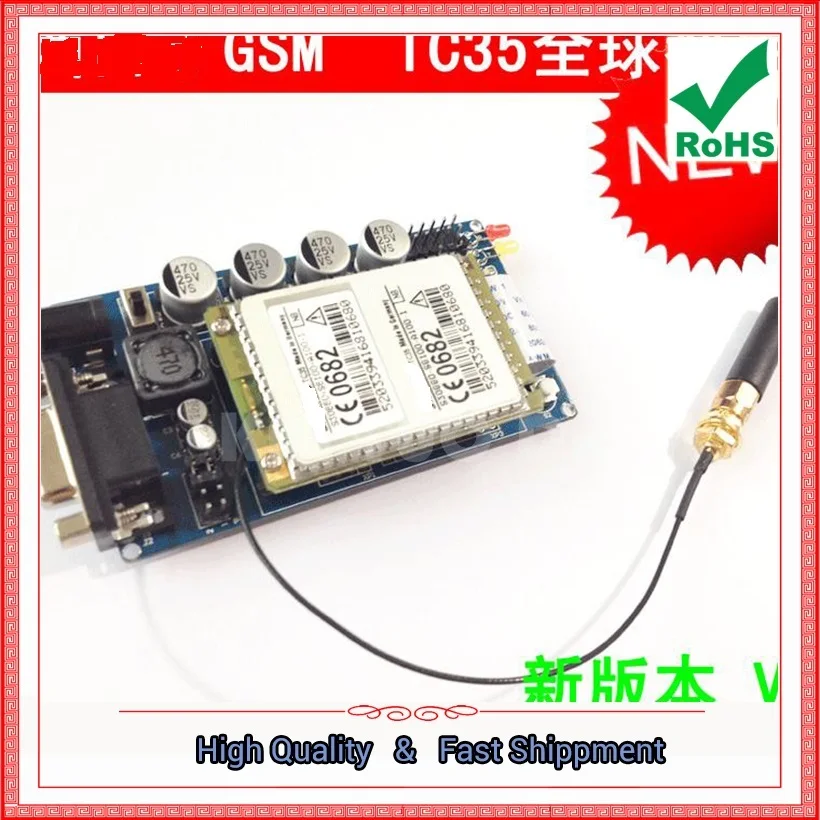
This GSM is made of Siemens TC35 products,Very stable, not afraid of comparison, This product is also very high cost, because weSend 12V1A power supplyOne.
The following are the same as the "This boardSupport 51, AVR, STM32, arduino, MSP430 and so onA variety of different company MCUs, andEach has its own personally tested code and the corresponding manualProvide, it is recommended to access the microcontroller to do GSM,Buy meThe
Manual Handle Operation:
1.TC35 module from entry to proficient.pdf:Http://pan.baidu.com/s/1bnAeBZx?qq-pf-to=pcqq.c2c
The above link needs to be copied to the browser to open, Taobao does not support external links
Information: http: //pan.baidu.com/share/link? Shareid = 389761863 & uk = 3543584085

Default shipping = TC35 motherboard (including antenna) + 12V1A power supply
Ultra-stable design, since the start 100% success.


Video Handle Operation:
1. New version of TC35 Introduction:Http://v.youku.com/v_show/id_XNzMxNjg0MDI4.html
2. MCU through three lines control module:Http://v.youku.com/v_show/id_XNzI5MzY0MTk2.html
OUR is superior to other store "development board".
1. The module starts automatically and uses the MAX810 auto reset to accurately meet the requirements of the Siemens module.
Several rough RC starts.
2. To meet the high-power requirements, if the power is not enough to cause the module dropped, the other party will call
Show that "you call the phone is not in the service area or can not be connected" and other inexplicable questions.This edition of four large
Power capacitors and a high-power inductors with a super-stable work.
3. Power Requirements, those using 3.3V small current Simple conversion chip power supply is unstable at 3.3V
There is a turnaround module appears power down situation. Module requirements voltage 3.3V-5.5V, for the sake of insurance election
Choose the voltage recommended by the Siemens manual.
4.PC serial communication, max 232 need to supply 5V. Use 3.3V to power the Siemens TC35 module
Is unstable, often serial port crash.
5. Power supply default is wide voltage 5-25V input,
6. Our design of the module circuit can be directly connected to a variety of external MCU, no need to level conversion, than
Such as STC89C52 with P3.0 P3.1 access to my board RX TX can be.
7. Our board with TVS, can be detected by EMC, anti-static impact board.
8. Our design has a power supply anti-reverse processing, do not worry about the wrong line caused a great loss.
The following describes the single-chip control GSM module method
1,51 Program code STC series and AT series [Pro test is not online copy, test software
KEIL2, KEIL3, Hardware AT89S52 and STC12C5A60S2]
2, AVR program code ATMEGA series[Pro test is not online copy, test software ICCAVR7.13, Hardware ATMEGA8 \\ 16 \\ 32 \\ 128]
3, MSP430 [[Pro test is not online copy, editing software IAR5.3 hardware M430F149]
4, STM32 program code STM32F103 series[Pro test is not online copy, test software KEIL4, Hardware STM32F103RBT6 \\ STM32F103RCT6\\ STM32F103RET6]
5, ARDUINO program code ARDUINO series[Pro test is not online copy, test software ARDUINO IDE, Hardware ARDUINO UNO]

The board on the TTL to do a simple level conversion pro-adapted to 51 AVR STM32 430 and other single-chip
The following describes the PC control GSM module TC35 method
The following describes the PC control GSM module TC35 method
1, to provide VB6.0 VC6.0 DELPHI JAVA C # VB.net PowerBuilder C ++ Builder SDK can be directly called. The following are the same as the "
2, to provide a full set of source code VS2008 C # test procedures to call and so on
3, to provide a full set of source VB6.0 can send Chinese and English, call, answer the phone, AT command test function
1, the GSM module has the following characteristics:
interface mode support serial port R232 and TTL adaptive.
work in EGSM900 and GSM1800 dual band.
Adaptive baud rate is 1.2kb / s ~ 115kb / s.
Supports voice and data signal transmission.
AT commands can be used to transfer instructions and data in both directions.
Supports Text and PDU format SMS.
Restart and failback can be achieved by AT commands or shutdown signals
comes with hardware reset, software reset and manual reset.
Compatible with multiple manufacturer modules.
2, application areasGSM module can be applied to the following occasions
Wireless terminal
Industrial monitoring and control (eg, wireless temperature and humidity monitoring and control of water level monitoring)
Remote meter reading system
Intelligent home control system
3, other instructionsPlease note the following when using the GSM module
Note that the polarity of the power supply should not be reversed
Note that the range and type of power input should not be mistaken
Note that the antenna must be connected when the GSM module is in use
Be sure to insert the SIM card when using the GSM module
PDF PCB can zoom in very clear

First, TC35 part of the debugging parameters
1, TC35 current consumption indicators:
1> TALK mode of peak, 1.8A
2> Typical mode of talk mode (TALK mode), 300mA @ 900MHz / 270mA @ 1800MHz
3> Idle mode (IDLE mode) current consumption, 10mA
4> Sleep mode (SLEEP mode) current consumption, 3mA
5> Power consumption (Power Down mode) of the current consumption, 50mA
2, on the LED lights show the state
SYNC pin can be used to output a synchronization signal (synchronization signal), can also be used in the application to control the output of a LED state. : SYNC side through a transistor or gate to control the LED. A simple circuit connection is: SYNC side through a resistor connected to the base of the NPN transistor (such as 9013), the emitter is directly grounded, the collector through a current limiting resistor connected to the negative LED, LED positive termination VCC. LED operating mode is completely similar to the synchronization signal, shows the working status of TC35:
1> LED off, indicating TC35 power off, in hibernation, alarm or simple charging mode
2> 600 ms On / 600ms off, the SIM card is not inserted, or the personal status is not registered / canceled, or the network is searching, or user authentication is in progress, or network registration is in progress
3> 75ms light / 3s off, that the network registration is successful (control channel and user exchange information is completed), no calls
4> LED lights, depending on the type of call: voice call, data call, in the establishment or completion of the state.
3, on the VDD side:
TC35 normal operation, the VDD pin output signal amplitude (about 60ms after the boot generated): 2.9V / 70mA, can be used as external applications.
Idle or talk mode: VDDout = 2.9V?% @ 70mA Imax = 70mA; Power off mode: VDDout = 0V.
4, on the VBATT + side:
TC35 operating voltage input terminal VBATT +, the voltage amplitude of 3.3V-5.5V, Vtyp = 4.2V, the maximum current Imax 2 A @ GSM antenna return loss (return loss) 6 dB. It must be noted that the minimum operating voltage can not be less than 3.3V, otherwise the voltage will drop, resulting in TC35 to stop working. Since the peak current of the VBATT + pin is 2A, a GSM transmission pulse may cause a significant voltage drop, and the inherent inherent impedance of the flat flexible connection of the external power supply may also be lost. Therefore, at any time, must ensure that the VBATT + voltage can not be less than 3.3V, and the voltage drop difference can not exceed 400 mV. In addition, in order to ensure that the voltage drop value of the TC35 in the transmitted pulse interval is at its minimum, a flat flexible FFC cable with a short connection module and a ZIF block shall be used with a length of no more than 200 mm and a low-impedance power supply.
5, on the POWER side:
TC35 charging voltage positive terminal POWER, if through an external power supply (such as charger) power supply, should ensure that Imax = 500 mA, Vin = 5.5-8V.
6, on / IGT (Ignition) side:
TC35 trigger the ignition signal / IGT, with the OC door or a simple switch to pull down the terminal level to open the module, active low. In the idle / talk / shutdown mode: Vout = 2.0V, Vlow, max = 0.45V @ Iout = 10, tlow 100ms. For the processing of the ignition signal IGT, it is necessary to first pull down the pin level to ground and maintain at least 100 ms.
Note that if you supply power via the charger circuit (connected to the POWER pin), or through battery power (connected to the VBATT + pin), then IGT?
7, on the PD (Power down):
TC35 off the power supply side / PD, shutdown signal pulse, the signal waveform ~~~ | ______ | ~~~, pulled low to low, at least 3.5 seconds to maintain effective. Vin, low, max = 0.45V @ I = 0.1mA, can be used OC door or a simple switch to achieve, through the shutdown signal can be closed TC35. And the IGT pin to apply a low-level pulse signal can re-open the module and the system. In addition, the shutdown signal terminal / PD can also be used to implement the watchdog signal output: Vout, low = 0.35V @ 0.01mA, Vout, high = 2.30V @ -0.01mA, fout = 0.5-2.0Hz
8, start TC35 way:
TC35 can be activated by the following way to start work
1> Triggered by ignition line IGT, into normal working condition
2> through the power cord, began to enter the charging area
3> through the RTC interrupt, start to enter the alarm mode
9, TC35 boot operation timing
When the application is started, the TC35 power-up process must be carried out as follows:
1> Until the VBATT + pin level exceeds 3.0V, the signal level of the line can be changed.
2> VBATT + feet up to 3.0V after the level of maintenance to maintain 10 milliseconds, before pulling down the IGT line signal level. The level drop time (falling time) of the IGT line must not exceed 1 ms.
3> In addition, the low level signal of the IGT line must be maintained for at least 100 ms.
4> In the IGT line signal conversion interval must ensure that VBATT + voltage can not be less than 3.0V, otherwise the module can not be activated.

С этим вором не связывайтесь Все что о нем написано хорошее он писал сам Держитесь подальше Он далеко от вас... Читать отзыв полностью...

Магазин №910733027 не советую иметь дело с этим магазином. Чистое кидалово. На запросы не отвечает. Все блокирует... Читать отзыв полностью...

заказала валенки 20.12.22 оплатила , водят за нос последнее прислали липовый трек номер компании СДЭК... Читать отзыв полностью...

Продавец DKGPD CCC мошенник и нагло лжёт. Отправил другому человеку с указанием моего номера телефона за мои деньги в другой... Читать отзыв полностью...

немного глупый вид.Некачественные швы портят весь вид... Читать отзыв полностью...

Yiwu Fente E - Commerce Co Store - недобросовестный продавец с Алиэспресс. 1 сентября сделала заказ (подарок ко дню рождения... Читать отзыв полностью...


Не прислали товар,вышли все сроки и обманули с возвратом денег.Аферисты,не связывайтесь с ними....... Читать отзыв полностью...